- #Arduino morse decoder lcd dsp goertzel software#
- #Arduino morse decoder lcd dsp goertzel code#
- #Arduino morse decoder lcd dsp goertzel license#
- #Arduino morse decoder lcd dsp goertzel series#
Also remember that the vast majority of microprocessors these days are electronically re-programmable, you can keep experimenting until you get the results you want and even use them for completely different tasks at a later date. Move the problem into the digital domain and it becomes a relatively simple task.
#Arduino morse decoder lcd dsp goertzel license#
I've held a Ham license for 50 years and progressed from 6L6 PA tubes to 30GHz HEMT amplifiers, I'm up to speed with latest developments but even with all that experience I wouldn't contemplate a Morse encoder in hardware alone.
#Arduino morse decoder lcd dsp goertzel software#
Remember that software is free and if it is the right tool for the job, use it. When a task becomes unreasonably complicated to do in hardware alone sometimes there is no option but to 'think 3D' and introduce some real-time decision making to solve it. It is as though you are asking to design a really simple car engine but it must have no moving parts. I appreciate what you are trying to do and the very noble reasons but some tasks just can't be done easily in hardware alone. I am not sure about this second approach. In this one, the EPROM parallel inputs will be connected to the shift registers and the EPROM output to some circuit, maybe a demultiplexer? to light up the relevant led.

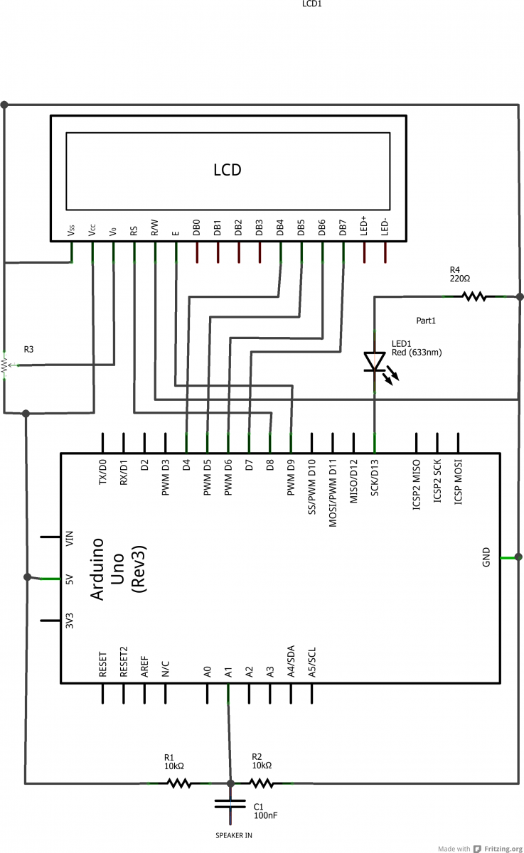
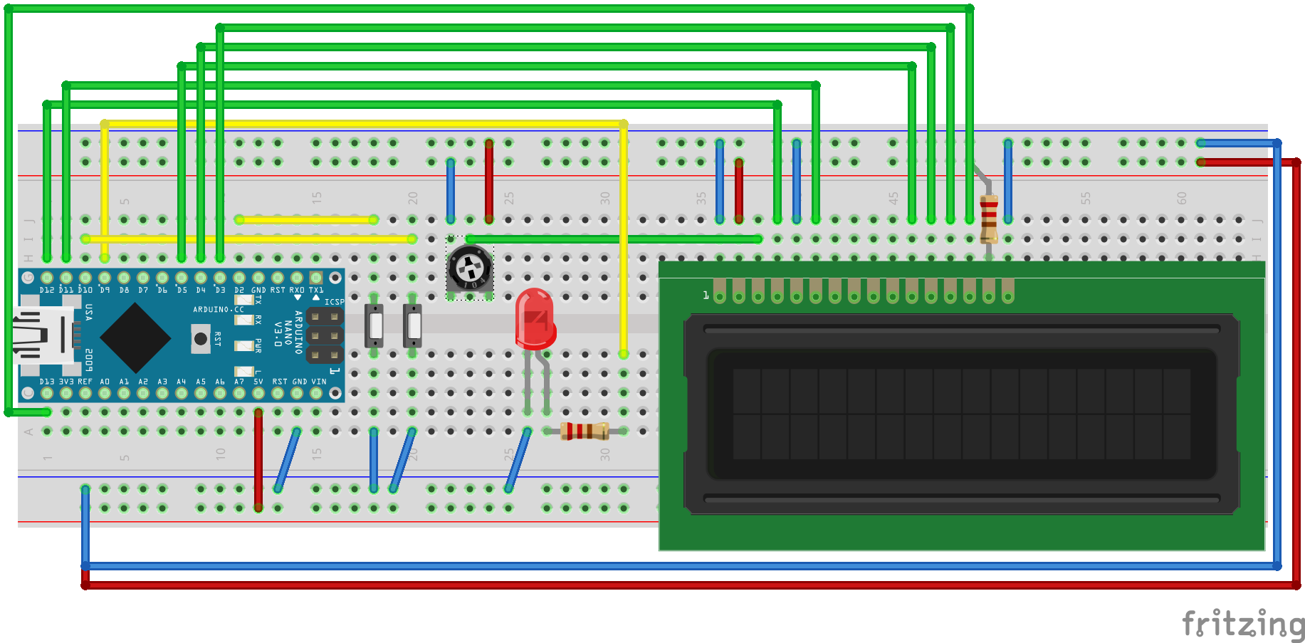
This is why I have thought of the EPROM solution. The problem is that you would need lots of demultiplexers for 36 symbols. Every few clock cycles a reset pulse must be present so as to reset everything and receive the next letter. for a input an LM567 can be used to convert audio tones to data. Then the specific LED will light up, representing the specific letter. Since there will be a unique sequence for each letter/number a specific output of the demiltiplexers will be set. Then now parallel output of the shift registers to go to demultiplexers. One or more shift registers that "record" the CW pulses. The BradtheRads approach is very interesting, but I was thinking of it as an MCU-less design. This is for the arduino project that VFONE posted above.
#Arduino morse decoder lcd dsp goertzel code#
To drag and drop them onto schematic, wire them up, and write code if necessary (this design Or change # stages, those changes are all trivial.Ĭhip has ARM processor, so if you want to use more of its resources and create moreĬomplex designs thats "normal" embedded work that is done with its IDE (PSOC Creator).īasically think of chip as a box of diverse parts, both analog (A/D, OpAmp, Comparator, PGA, DAC.)Īnd digital (from simple gates to LUT, PWM, Timers, DDS, Quaddecoders.), and a tool that allows you

Onchip debouncer used to condition the switch. Note most of chip resources unused in this design, see right hand window used/available Board has programming interface on it (USB to PC).īasically you drag and drop chip resources out of its catalog, wire up with a wizard, Only code needed is chip startup code, and that isĪuto generated for you. If you wanted to try BradtheRads approach, this can be done with a single chip.Īll but R's and LEDs and Switch are onchip. Or to translate to ascii in case you want to send to a computer. This may be used for 7-segment display (maybe scrolling, maybe stationary). Or, create a binary lookup array (in the form of electronic memory cells, or diode-resistor pullup pairs). The letter appears only momentarily as the next letter comes in with little pause. The obvious way is to light an led behind a translucent panel with the letter painted on it. To display each letter is the second challenge.
#Arduino morse decoder lcd dsp goertzel series#
Where the last choice stops is the result of the unique series of dots and dashes for that letter. (I pressed my keyboard keys to increase or decrease timeframes.)Įxample, if the first beep is a dot followed by a gap, you have letter E. Follow the right when a beep is a dash (greater than 12 mSec).Įnd a character when the gap is 25 mSec. (There are at most 5 steps or levels, assuming you make do with 32 characters.) Follow the left path when a beep is a dot (less than, say 12 milliSecond). The switching becomes complex, but it's one way to pursue proof of concept.Ĭreate an electronic branching structure based on whether a dot or a dash is encountered at each step. The output is a series of dots and dashes. Apply a network to a shift register (as an alternative, one or two 4017 decade counters). To make a gap apply a pull-down resistor.

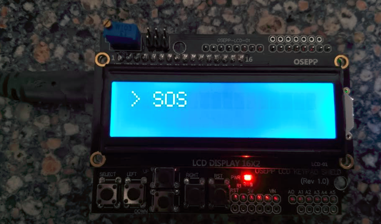
Otherwise you need to create artificial memory cells and artificial binary words.Įach character (dots and dashes) can be stored as a series of diode-resistor pull up networks. The job is easier with a computer of course. It successfully translated beeps into English text onscreen.

I developed my own morse decoder years ago for my Commodore computers.


 0 kommentar(er)
